Some Preventative Maintenance With Old Electronics
During the fall of last year, I ended up spending a significant amount of time working with the various old electronics I have sitting around at home. This included game consoles, game cartridges, monitors and PC equipment.
I'd known for quite a bunch of years now that there was a bunch of preventative maintenance that I needed to do with most of these things, but I kept putting it off. This is mostly because I didn't think my soldering skills were really up to the level that would be, I assumed, needed for all but the simplest of the work to be done. I'd done simple soldering work before, like replacing the save game batteries in some of my game cartridges that had died.
I'd actually only attempted one complex soldering job before, back in 2018. This was replacing all the electrolytic capacitors in an old Enermax EG365P ATX power supply, which is a PC power supply from ~2000-2001-ish and thus is right in the prime of the capacitor plague era and so was it was pretty important to do this work before putting it to use. The capacitors inside it didn't visually look dead at least, but they were all known "junk" brands.
This project with the Enermax power supply was actually what prompted me to go out and buy a fancy desoldering gun (one with a built-in vacuum pump to suck the solder away quickly and cleanly). At the time, I went to a local store here in Toronto and bought what they had, which was some generic Chinese model "S-993A" which from what I can tell now doing some quick searching, just seems to be a model that is available under multiple different brands. It was relatively cheap compared to other desoldering brands, such as the ones Hakko sells. And because it was the only one that the store I went to had, I grabbed it.
The difference going from using a hand-pump desoldering tool to using this new desoldering gun was a very real night-and-day type of difference. I made quick work of the remaining Enermax electrolytic capacitors and replaced them all, after doing some research on what types of capacitors I needed to buy (a confusing and intimidating topic to read about for someone without an electronics background). Powering it up for the first time was sweat-inducing as I was half-expecting smoke or fire or something ... but it powered up without any problems, and it still works great today!
So, with that job under my belt, I had a motherboard that had some capacitors on it that were noticeably bulging and needed replacing. I figured "how hard can this be?" and proceeded onward. What I didn't know was that the PCB of your typical computer motherboard is kind of different from the PCB that was in the Enermax power supply I had just worked on. As I understand it now, computer motherboards are multi-layer and there's a ground plane that runs through the board. This effectively acts as a heat sink and makes desoldering components, even with a fancy desoldering gun, extremely difficult if you aren't prepared! And I was not prepared! That exercise ended up with a trashed motherboard unfortunately, and it really put me off the idea of attempting jobs like that in the future.
So, fast-forward to 2022. I dust off my Sharp Twin Famicom for no particular reason other than that it's a cool looking console and I wanted to use it for a while instead of the Famicom AV that I'd been using. Because reasons. Both of these consoles are RGB-modded by someone else (which for reasons described above, I did not think myself capable of doing this mod). When both of these consoles were modded, they were set up with a three-way toggle switch for controlling which palette the conosle used. After setting up the Sharp Twin Famicom, I noticed that the colours were intermittently flickering back to the default palette. It seemed like a tell-tale sign of a poor connection somewhere, likely with the palette switch. So I opened it up. Sure enough, I noticed that the 3 wires going from the palette switch on the back of the console to the RGB mod PCB that is hooked up to the mainboard had been accidentally pinched by the plastic standoffs on the inside of the case. Oops. The wires would need to be replaced.
As I was inspecting the inside of the console, I was noticing how dirty the mainboard seemed. And then I realized that actually, some or most of the "dirt" seemed to be electrolytic residue that was leaking out of a couple of the capacitors on the mainboard.
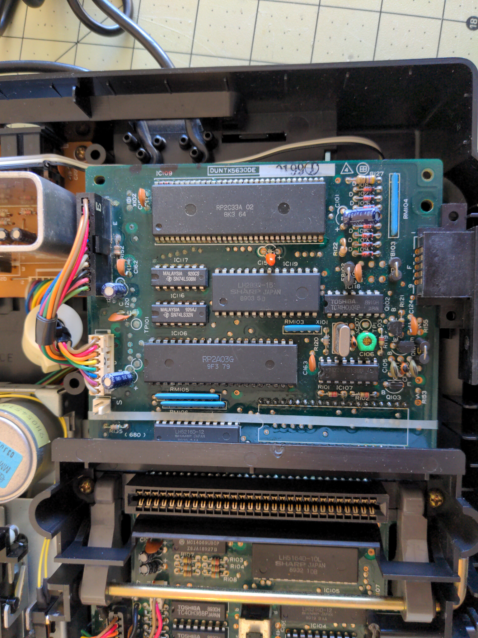
It can be a bit hard to see at first glance (wish I'd taken this photo closer up... oh well), but around the top-left area of the mainboard, near the two long cable connectors, there are two blue electrolytic capacitors. And if you look at the surrounding components, especially the resistors and ceramic capacitors, you can see some green-ish powdery reside around the solder joints on the PCB. And if you look at the surrounding chips, you can see some small bits of the same powdery type of residue on the closest solder joints of those too.
The console itself was still working just fine (other than the aforementioned colour palette switch), but if left unchecked, this slowly leaking electrolytic fluid would cause damage to other components. Plus it's a sign that the capacitors (at least, the ones leaking) are past their best-before date.
I decided that I was going to try to do this clean up job myself. I don't really know why, as the memory of my failure with the motherboard several years earlier was still there. But I guess that I knew I kind of needed a big project to work on and also the growing belief in the back of my head that if I was going to keep 20-30+ year old electronics around, I really did need to get more confident with a soldering iron at the very least.
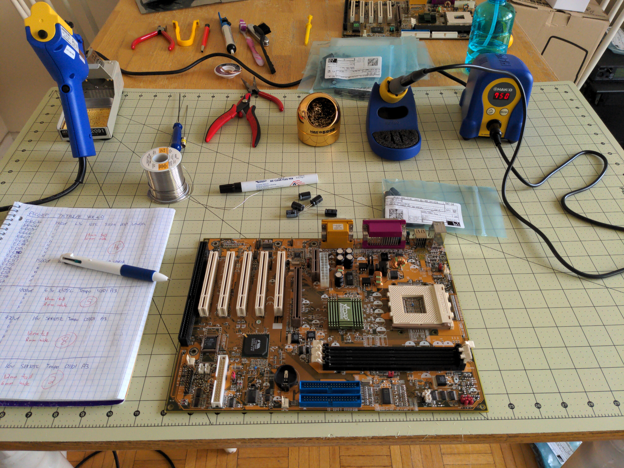
So, the next step seemed clear to me. I needed to clean up the mess. And the best way to do that (in my mind anyway) was to remove all the components in the affected area around the mainboard:
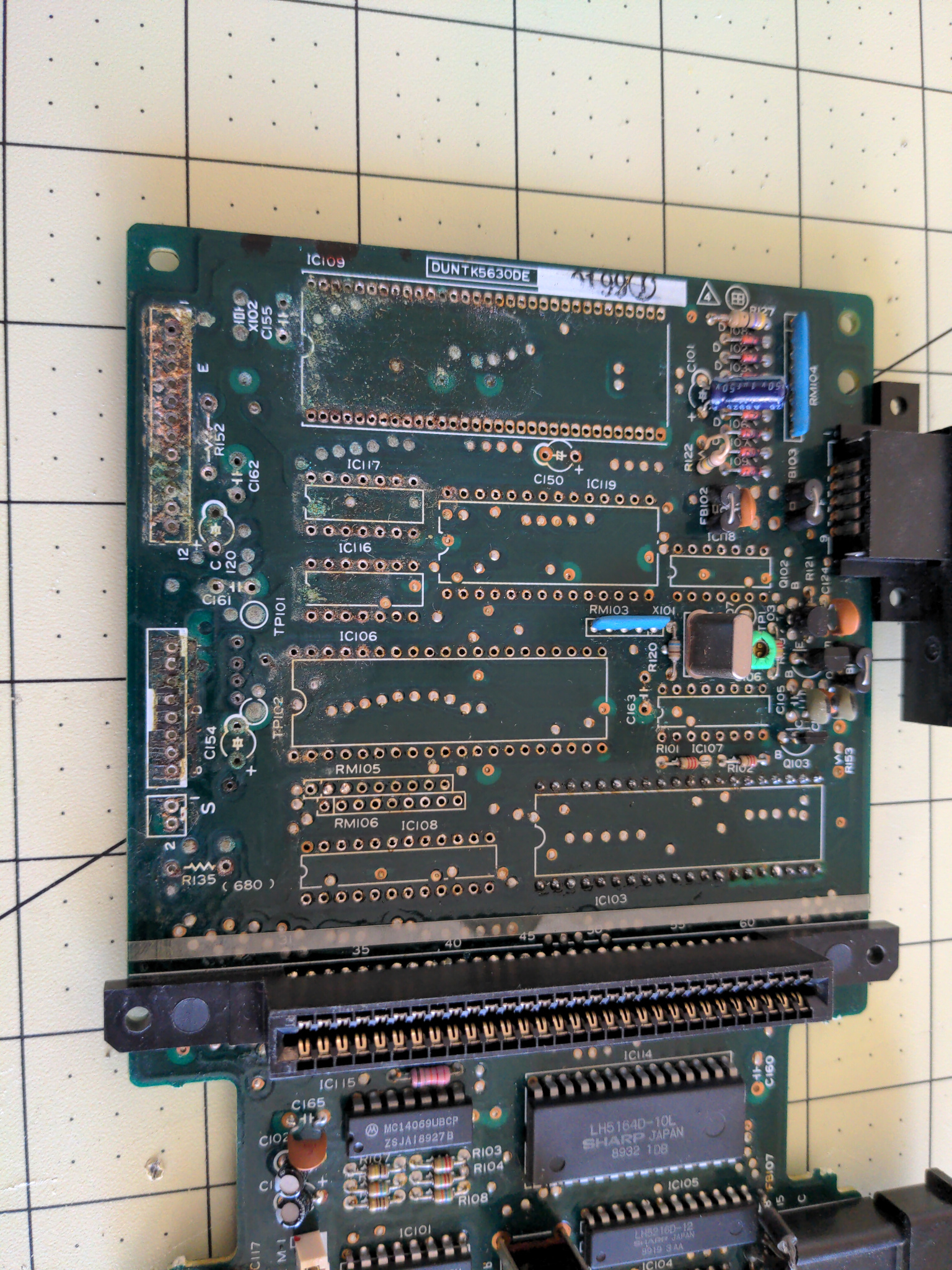
There's a lot of built-up dirt from over the years, but you can see more of the powdery electrolytic reside also. I'll also say that removing that top chip, labeled "IC109", was pretty intimidating to me. It all went better than expected. Putting it back later, and soldering all the leads which are very close together was a challenge for me. At the end, I ended up testing for bridging between each lead with its neighbours with my multimeter.
Of note in this picture, the chip labeled "IC103" in the bottom-right area just above the black cartridge slot is the space for the PPU. As part of the RGB mod for Sharp Twin Famicoms, you actually install a little adaptor socket and mini PCB on the underside of the mainboard and then the PPU chip and RGB mod PCB then fits on the underside of the mainboard when installed. This is due to space constraints in the Sharp Twin Famicom and for whatever reason, there is a ton of empty space in the bottom of the console when it is all assembled together. I just point this out to note that I did not remove "IC103." But even still some of the components towards the right edge of the mainboard (like the two smaller chips labeled "IC107" and "IC118") didn't need to be removed. I was just being very overly cautious when it wasn't warranted. Heh.
Anyway, during this process of removing all these components, my desoldering gun clogged up! Included in the original package when I bought it were too long thin metal cleaning rods that you're supposed to be using diligently during normal use to ensure the tube that the solder gets sucked up, through the soldering iron tip into the plastic chamber, is clear. I was using this cleaning rod all the time, but even still, I finally encountered a clog. The cleaning rods provided were completely inadequate to remove the clog as the clog is literally hardened solder stuck in the tube.
I had a big set of tools given to me many years agp, and included inside this tool set was a large number of different drill bits (I don't have a drill though, heh). I noticed that the smallest of these drill bits was just small enough to fit in the hole of the desoldering gun. In hindsight, this was a dumb decision, but I decided to place the drill bit in the hole and then very lightly tap on the end with a hammer to clear the clog. This worked fine and I continued on with my desoldering work. But then it clogged again. And I cleared it again with the same procedure. And then it clogged again. And this time, when I tapped on the drill bit with my hammer, the drill bit snapped in two and one half of the bit was stuck in the desoldering iron tip, flush with the top, therefore there was nothing to grab on to in order to pull it out. I was unable to remove the stuck drill bit piece.
Frustrated and unable to find any replacement desoldering iron tips anywhere for this particular desoldering gun that I had, I decided I needed to bite the bullet and get a better quality desoldering gun that had an ample supply of manufacturer-provided replacement parts and other accessories available.
The soldering iron that I bought back in 2015 is a Hakko FX888D which I really like. There are tons of replacement parts available, and I do own a few different soldering tips for it. Hakko, while pricey, at least does provide you with all the replacement parts and accessories you could want for their stuff. I was aware of their desoldering gun before I originally got the Chinese "S-993A" that I had, but the Hakko desoldering gun cost over twice as much! But, as the saying goes, "you get what you paid for." So, I went ahead and purchased the Hakko FR-301.
And let me tell you, the difference in how the FR-301 works as compared to the S-993A was again, basically night-and-day feeling to me. I don't think I even realized how poor the heating element was in the S-993A was until using the FR-301. I never measured the temperature of it, but now I'm quite sure that the S-993A was probably never operating at the temperature it was set to, likely always a fair bit cooler in reality. As well, the suction power of the vacuum seems like it is better on the FR-301 which is important for sucking away molten solder before it hardens again. Finally, the build quality of the FR-301 is clearly better. The plastic shell of the S-993A always looked like it was barely fitting together in some places to me. I was half-worried it was going to start coming apart in time. The FR-301 just feels like a very solidly built tool through and through.
That said, the best part of the S-993A is the stand that it comes with. It's this really solid metal stand with some weight to it. The "stand" that the FR-301 comes with is a bad joke in comparison. Thankfully, the FR-301 fits into the stand for the S-993A just fine.
Oh, and Hakko even sells a special tool for dealing with desoldering tips that are clogged up. You better believe I bought one of those too. Heh.
Anyway! With the tools situation all sorted out, I returned to my work on the Sharp Twin Famicom console and finished desoldering the remaining components so that I could fully clean away the gunk from the mainboard. I also purchased a replacement capacitor kit from Console5 who is well known in the retro-gaming community for providing good quality "cap kits" for a large number of consoles and accessories.

I also took the opportunity to replace the electrolytic capacitors in the floppy drive and the power PCB. None of the other capacitors were leaking like the two on the mainboard, however. As well, I replaced the three wires for the 3-way palette switch that originally prompted me to open up this console in the first place.
And thankfully, all these efforts were not wasted at the end, as after re-assembling the console and powering it on ... it worked! Hooray!
I feel obliged to point out that the original capacitors that were leaking in my Sharp Twin Famicom were Nichicon capacitors. Nichicon is regarded as one of the top-tier brands of capacitors that you can buy. Even still, electrolytic capacitors will all eventually fail given enough time and wear regardless of the brand.
I point this out mainly because this whole experience with my Sharp Twin Famicom really changed my point of view on old electronics like this. If you spend a bunch of time reading about this stuff on various forums, etc you will often come across people spouting common sayings like "if it ain't broke, don't fix it" when people ask if they should worry about replacing electrolytic capacitors in their 20-30+ year old electronics. I'm certainly not an expert here, but my own experience here has taught me now that there's probably some value to the idea that if you wait until something breaks, you may end up with a bigger job (not to mention some harder to replace custom components that might end up damaged) than if you had just said "hey, this thing is over 30 years old, maybe I should think about some preventative maintenance so that it has better odds of continuing to work for the next 30 years."
I feel like I got very lucky here by discovering this problem before it caused real problems. And it prompted me to perform similar preventative maintenance on some more of my old game consoles, including two SNES's, a Famicom AV and Famicom Disk System, and a Sega Genesis. I still have more to do.
One nice side effect of this job though, was that I was starting to feel a lot more confident in my soldering abilities. I had a couple old computer motherboards from the "capacitor plague" era that also needed their electrolytic capacitors replaced, and decided that it was about time to try this again. But first I'd do some reading on the subject to see what other people's techniques for this are.
One that I read about, was using a heat gun to pre-heat the motherboard around the area where you need to desolder components from. I had a cheap-ish heat gun that I originally bought for working with "heat shrink" I was using for some very simple custom cables I made for something some years ago. I gave this technique a try with my candidate motherboard, and ... yeah, big difference from before! It really changed the entire process to "stupidly easy." Also applying generous amounts of flux beforehand also helps a great deal (which is basic "soldering-101" type of stuff).
Made quick work of that motherboard and it's now working great! Also took care of a couple other motherboards afterwards.
And then finally, this gave me the confidence boost I needed to tackle the really big projects I had on my list. Doing the same capacitor replacement preventative maintenance work with the CRT monitors I have. Oh boy!
Taking apart a CRT is potentially dangerous (in a lethal kind of way), as there is the potential that the tube (and some of the capacitors also) could be holding onto large amounts of electrical charge even after powered off. Sometimes, even a long time after it's been powered off. As well, CRT monitors have a ton of internal components and interconnected boards inside them that can be very complicated to disassemble and then reassemble properly. Basically, there's lots of potential for things to go wrong here.
I spent a week or so reading up on the process as well as watching videos. But I'll admit that I still was sweating quite a bit the first time I went to discharge the tube with my home-made tool.
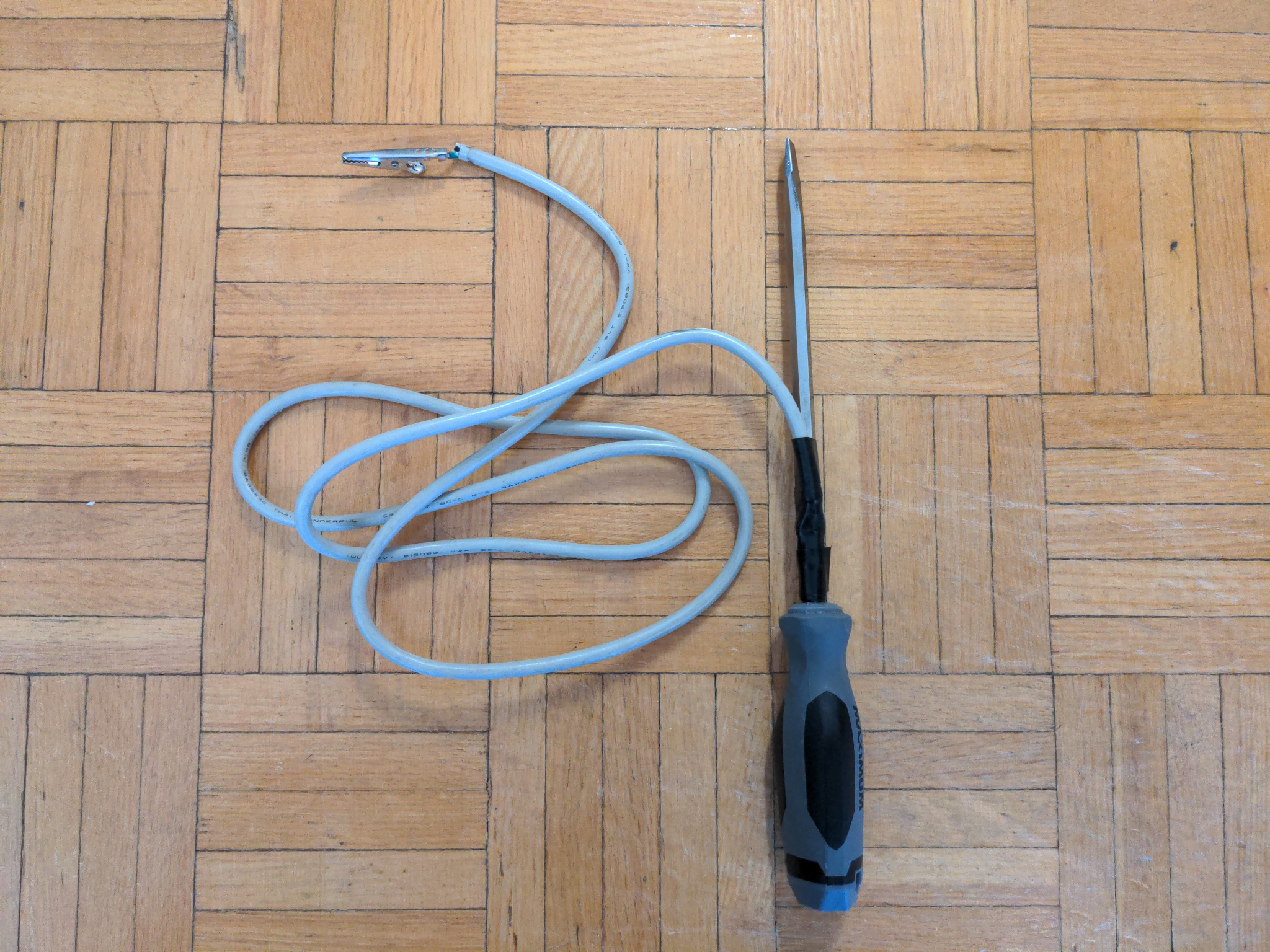
Yes, this is what I used. Really. Heh. You can find a lot of videos on the topic, it's not as crazy as it might seem at first glance.
The monitors I ended up working on were all Sony monitors actually. Each of these monitors was working fine initially, but in some cases the geometry of the picture was noticeably off and difficult to get dialed in to "good" settings via geometry adjustments. As well, one monitor had a very noticeably weak internal degauss coil.
- CPD-100SX (15" PC VGA monitor)
- CPD-210GS (17" PC VGA monitor)
- PVM-14M4U (14" professional 240p/480i monitor)
- PVM-20M2MDU (20" professional 240p/480i monitor, medical variant)
- PVM-20L2MDU (20" professional 240p/480i monitor, medical variant)
Why do I have so many monitors? Don't ask me that question. This isn't even the full list of what I have right now.
The two VGA monitors were the worst to work on I think. They each had significantly less capacitors in total as compared to the PVM monitors, which all had over twice as many. But the VGA monitors did not seem to have been designed in a "service friendly" way and were highly annoying to disassemble and then reassemble. The PVMs are these big bulky boxes in comparison and look like they were designed with a "function over form" mentaility from the outside ... they are clearly designed to be serviced and while the process of disassembling is not super easy, I do think it is significantly more straight-forward with them.
What I found helpful for all of these was to take a ton of pictures before taking anything apart (after you have the case/shell off, of course) as well as taking a video where you slowly pan around the entire thing, 360-degrees around, being sure to get good, multiple angles on all the components you can. If a picture is worth a thousand words, a video like this is worth a million words. There were multiple times during reassembly where I realized that the pictures I originally took were not good enough, to the point where I was basically only referencing the video.
Additionally, because the PVM monitors had sooo many capacitors in them that I was replacing, that in addition to the detailed notes I was taking on paper as I was removing capacitors, I ended up preparing special pictures from photos I took of the PCBs with labeled circles for each of the capacitors (see here and here as an example). This was super useful while I was installing the new replacement capacitors, as I had my original paper notes and these labeled photos to double-check that what I was installing was going into the proper location (and with the correct orientation). During the initial removal process I was being super detailed, triple-checking what I was writing down to make sure I didn't make a mistake. With so many capacitors involved, I figured the odds of my making a mistake if I was rushing through the process would be really high.
Figuring out what capacitors to get as replacements was also quite the learning exercise. I'd been down this road before to a limited extent with the Enermax ATX power supply I worked on a few years ago, but that was significantly more straightforward (with significantly less capacitors in total). People have shared capacitor lists for some of these monitors, like the PVMs. But there are some minor revisions and differences. Even comparing the service manuals that you can find online for these that have full detailed electrical component lists showed some minor differences between what I had. And it makes sense that during the lifetime of these things that the manufacturer makes some revisions along the way to fix issues that are discovered. So I was more than a little wary of using some else's list and that was a big part of the reason I opted to take really detailed notes as I was removing capacitors where I was recording the capacitance, voltage, brand, any other markings on the capacitor (e.g. series name), temperature rating, width/diameter and height.
You can find discussions out there with people talking about putting in replacement capacitors into these monitors that are all "low ESR." After looking up the datasheets for the capacitors that were originally used in these monitors, very few of them are actually "low ESR" series. I'm absolutely not qualified to speak about is the best approach here and the tradeoffs, etc. But I decided that what I would do is stick as close as I could to what the manufacturer had used, with the one exception being that I would bump up the temperature rating for all of my capacitor replacements to 105 degrees celsius, up from 85 (for the original capacitors that weren't already rated 105 anyway, which was less than half). But otherwise, I did my best to match up capacitance, voltage, and physical dimensions and then comparing datasheets to understand the general properties of what the original capacitor series were (by far the majority were just "general purpose" types, nothing special about them) and then find a matching replacement from a known top-tier brand (which for me was Rubycon, Nichicon, or Panasonic).
In the end there was only one capacitor that I could not find any suitable replacement for, so I opted to leave the original in. The PVM 20L2MDU monitor's "C617" capacitor on the "G" board has leads that are in this weird almost L-shape arrangement (one lead being perpendicular to the other) that I just could not find any replacement for anywhere. I'll have to give that one some thought down the road and probably hack something together, but the original capacitor is still working fine for now.
I do think that all this preparation work and detailed note-taking was very worthwhile as, much to my amazement, each of the five monitors I worked on, once the replacement work was done and the monitors reassembled, worked perfectly the first time I powered each of them up! I absolutely did not expect this. Each time I powered up one of these monitors for the first time after reassembly, I was absolutely expecting smoke, fire, sparks, or something generally bad. Maybe I just got lucky, heh.
After finishing up with each of these monitors, the first thing I did after ensuring they powered on fine, was to immediately go and do a factory-reset with their internal settings. Since I had made custom geometry alterations to each before, and with a full set of new capacitors, some of the geometry issues could be fixed up now.
The biggest differences I noticed were with the CPD-100SX and CPD-210GS. The CPD-100SX in particular was a very worn monitor when I got it. To get a comfortably usable picture on it, you basically needed to turn the brightness and contrast up to maximum. And even then, it can be a little dark looking at times. After the capacitor replacement work was done, the monitor still seems to be about at the same level of brightness (maybe a tad bit better), but the biggest difference was the geometry is now excellent with default settings, and the warm-up time after initially powering the monitor up was significantly reduced. Plus, the internal degauss coil, which sounded very weak before, now sounds "normal" to me (roughly the same as the other monitors I have). The CPD-210GS also saw similar geometry improvements, but nothing else to note.
The PVM monitors didn't really seem to gain any improvements after the replacement work was done, but to be fair, each of them looked really good beforehand. There were some very minor geometry improvements with the 20L2MDU, but nothing significant.
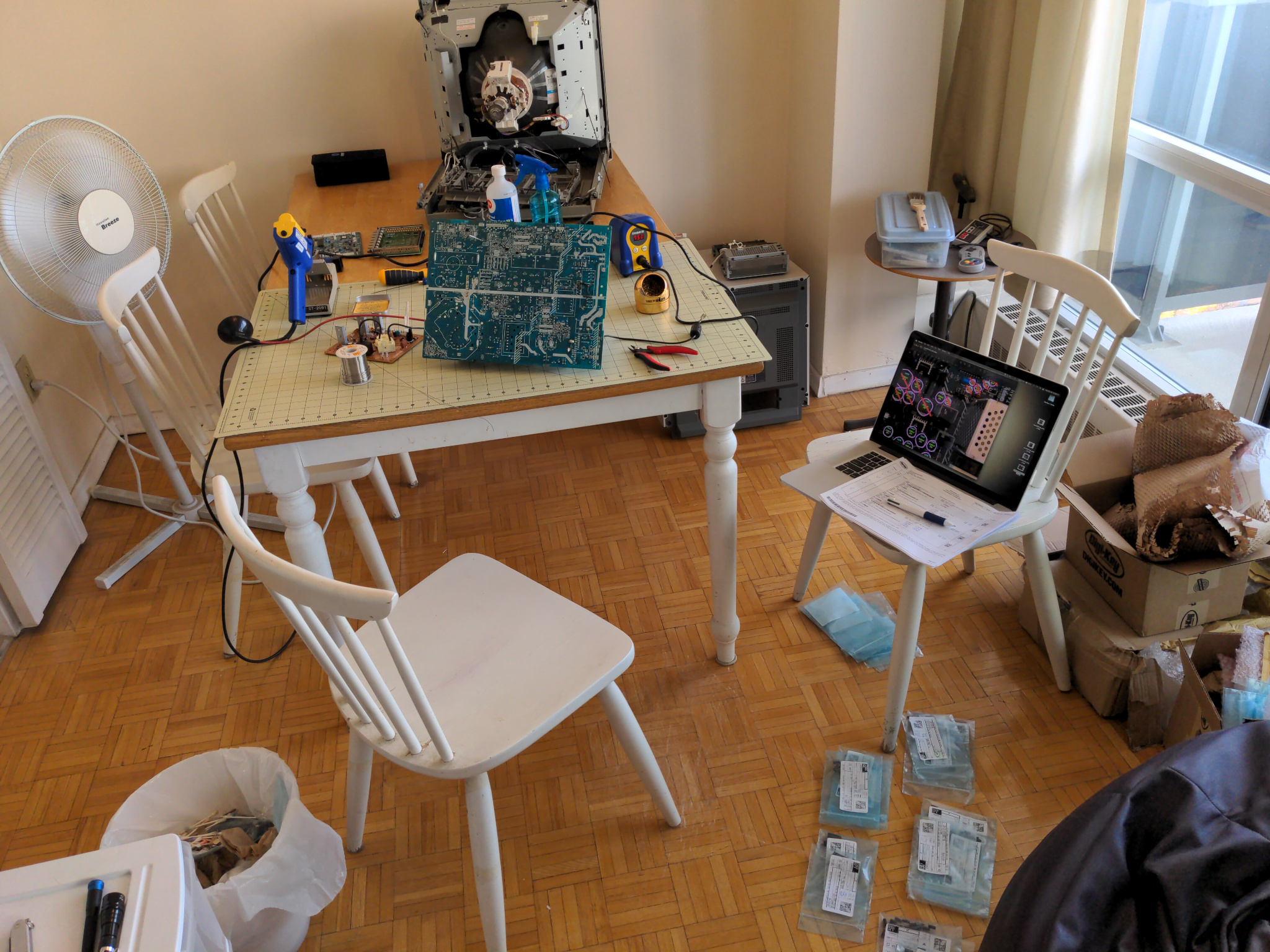
The end result of all this work however, is that after two months, I could finally reclaim my dining room table which looked something like this the whole time as I worked on all of these projects.